MIL-DTL-24688A
APPENDIX A
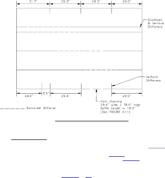
FIGURE A-2. Reflected overhead view of stiffener arrangement.
A.3 TEST PIPE CONFIGURATION
A.3.1 Test pipe configuration. The insulated pipe configurations shall be installed inside the test compartment
in a manner that provides a vertical run of piping in the corner area above the ignition source, and as this vertical run
meets the overhead, the run changes into a horizontal pipe run across the overhead of the compartment. Figure A-3
provides a sketch of this arrangement. The pipe configuration shall consist of five ½-inch inner diameter pipes
installed as a closely spaced pipe bundle. The test configuration is shown on figure A-4. Each pipe run shall be
5 feet in length for the vertical portion and 10 feet in length for the horizontal portion. Figure A-5 provides a sketch
of the construction of the pipes. The pipe runs shall be supported using ½-inch steel angle welded vertically to the
ceiling of the compartment. Horizontal supports for the piping shall be attached to the vertical segments using
¼-inch bolts. The pipe runs shall be secured in place at each support using wire tied to the cross supports. The
support locations and details are provided on figures A-4 and A-6. The geometric center of the vertical run shall be
centered over the wood crib.
22
For Parts Inquires call Parts Hangar, Inc (727) 493-0744
© Copyright 2015 Integrated Publishing, Inc.
A Service Disabled Veteran Owned Small Business