MIL-DTL-24688A
APPENDIX B
B.3.2 Insulation thickness. Vent duct insulation material shall be applied at a thickness of 1 inch.
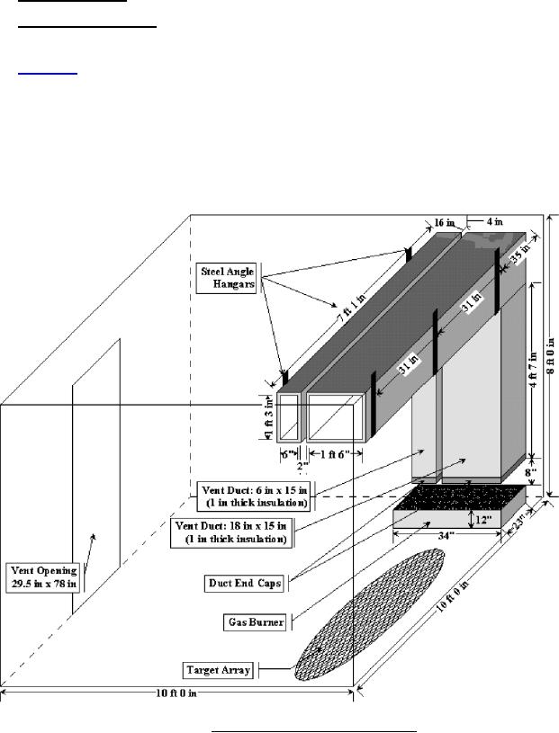
B.3.3 Installation configuration. The insulated duct configurations shall be installed inside the test
compartment in a manner that provides a vertical run of ducting in the area above the ignition source, and as this
vertical run meets the overhead, the run changes into a horizontal duct run across the underside of the compartment
overhead. Figure B-3 provides a sketch of this arrangement. The finished sides of the insulated duct configuration
shall be 16 inches from the left wall, 14 inches from the back wall, and 4 inches from the overhead. There shall be a
2-inch separation between the finished sides of the two insulated ducts. The finished bottom of the vertical ducts
shall be 8 inches above the top surface of the burner.
B.3.4 Test duct supports. The duct runs shall be supported using ½-inch steel angle welded vertically to the
ceiling of the compartment or equivalent supports. Horizontal supports for the ducts shall be ½-inch steel angle
attached to the vertical segments using bolts.
FIGURE B-3. Drawing of duct insulation test set-up.
30
For Parts Inquires call Parts Hangar, Inc (727) 493-0744
© Copyright 2015 Integrated Publishing, Inc.
A Service Disabled Veteran Owned Small Business